
The aim is to prevent voltage surge from being directly conducted from LPZ0 to LPZ1 and limit the voltage surge varying from tens of thousands of volts to hundreds of thousands of volts to 2500-3000V.
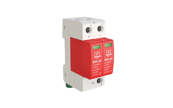
Three-phase voltage-switching-type power LPS should be installed in the low voltage side of the voltage transformers at the entrance as the type 1 protection, allowing for at least 60KA of lightning current range. Given it serves as a bridge between the earth and all phases of lines into users' power supply system, the system, or CLASSIC power LPS, should have a capacity as high as over 100KA of limp per phase and a limited voltage less than 1500V. These electromagnetic LPSs are specifically designed for inducing and withstanding lightning. For details, they are responsible for absorbing the high energy of surge by diverting much of it to earth. CLASS lightning protector works to absorb large current surge under a medium-level voltage; therefore, it fails to protect sensitive electrical equipment inside the power supply system on its own.
The type 1 lightning protection unit can protect against lightning of 100KA or 10/350μs, which meets the highest protection standard by IEC. Here are the technical references: current range ≥100KA(10/350μs); residual voltage ≤ 2.5 KV; response time ≤100ns.
The aim is to further limit the residual voltage surge after the type 1 LPS protection to 1500-2000V and achieve equipotential bonding between LPZ1 and LPZ2.
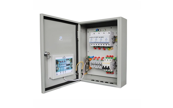
Voltage-clamping-type power LPS should be installed at the lines from distribution boxes as the type 2 inverter lightning protection, allowing for at least 20KA of lightning current range. More specifically, it should be installed at the sub-distribution sites supplying power to important or sensitive electrical equipment. These LPSs can further absorb residual surge energy after the entrance of the user supply system, greatly suppressing the transient overvoltage. The power LPS as the type 2 protection is also called CLASSII power LPS, should have a capacity as high as over 45KA of limp per phase and a limited voltage less than 1200V. For general user power supply system to run equipment, a combination of the type 1 and type 2 LPS protection is enough.
The type 2 power LPS protection has adopted class C protector to provide full-mode protection including phase-center, phase-earth, and center-earth model. Here are its major technical parameters: current range ≥ 40KA(8/20μs); residual voltage peak ≤ 1,000V; response time ≤ 25ns.
The aim is to protect the equipment by making the residual voltage surge below 1000V and ensuring its energy will not damage the equipment.
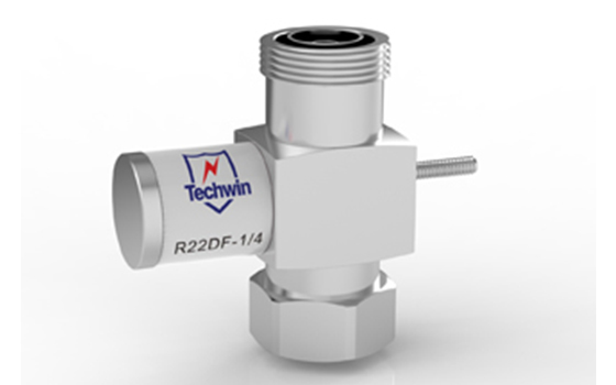
Series voltage-clamping-type power LPS should be installed at the incoming line ends of AC power of electronic information equipment as the type 3 protection, allowing for at least 10KA of lightning current range. To eliminate the transient overvoltage, a LPS can be provided for the internal power supply within electric equipment. The LPS should have a capacity of at most 20KA of limp per phase and a limited voltage less than 1000V. It's necessary to set the type 3 LPS protection for some extremely important or sensitive electronic equipment, which can meanwhile prevent the equipment from the impact of transient overvoltage generated by its internal system.
For rectifier power supply adopted by radar equipment, microwave communication system, and mobile communication base station, a DC power LPS should be selected as the final protection based on its operating voltage that matches the specific protection needs of the equipment.
According to the voltage-resistant level of the protected equipment, Type 1 and type 2 LPS protection will be enough if their limited voltage is less than the withstand voltage of the equipment. More types of LPS protection are necessary if the withstand voltage of equipment is quite low. The type 4 LPS protection should not be less than 5KA of lightning current range.
 Beyond the Basics: Advanced Features in Surge Protectors for Tech EnthusiastsJanuary 5, 2024Unleashing the Power of ProtectionFor tech enthusiasts who revel in the intricacies of their electronic ecosystems, surge protection extends beyond mere safety—it becomes an art, a science, and an in...viewDo surge protectors work against lightning?April 27, 2025Although surge protectors cannot directly prevent lightning strikes, they can significantly reduce the damage caused by lightning strikes to electrical equipment and circuits. As a specially designed ...viewInstallation Steps of The Surge Protection DeviceAugust 30, 2021Ⅰ. Tools of installing a surge protection deviceBefore installing the surge protection device, tools such as a flat-blade screwdriver, a pair of wire strippers, some pliers and electrical tape are ne...viewWrong‑mounted SPD Equals No SPD at AllSeptember 1, 2026Many users focus heavily on parameters such as discharge current capacity, protection level and product class when selecting a Surge Protective Device (SPD). Yet they tend to overlook an equally criti...viewWhat Are the Lightning Protection Devices?September 18, 2021The whole set of lightning protection devices can be divided into flash catcher, lead wire, lightning protection and grounding device. Lightning protection device is to prevent the equipment from bein...viewTechnical characteristics of SPDSeptember 8, 2021The important technical characteristics of SPDMaximum continuous operating voltage UCThe maximum continuous operating voltage (old: rated voltage) is the maximum root mean square value (rms) of the al...view
 EN
EN
 jp
jp  ko
ko  fr
fr  de
de  es
es  it
it  ru
ru  pt
pt  ar
ar  vi
vi  th
th  ro
ro  bg
bg  nl
nl