
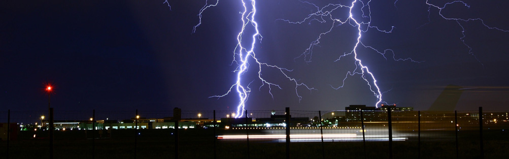
During the final acceptance inspection of many electrical projects, we often see a puzzling situation: “Everything seems to be done, but the system remains unstable.”
Equipment is installed, surge protective devices (SPDs) are in place, grounding resistance tests pass – yet the system still suffers from frequent issues: communication anomalies, device reboots, or even complete burnouts.
The problem is not whether lightning protection is installed. It is that a critical step is done incorrectly – or not done at all.
Many designs and installations focus on the “visible” aspects:
How many stages of SPDs are installed
Whether grounding resistance meets standards
Whether lightning rods are present
But the factor that truly determines system safety is more fundamental: equipotential bonding.
Lightning protection is not just about diverting the strike – it is about keeping all equipment at the same potential so that no destructive breakdown occurs.
When lightning current dissipates into the ground, a typical phenomenon occurs – ground potential rise.
If the system has the following conditions:
Equipment is connected to different grounding points,
And those devices are also interconnected via power or signal cables,
Then when a lightning strike happens, a potential difference is created.
The result is:
Potential difference + conductive path = equipment breakdown
Many equipment failures are not caused by a direct lightning strike, but by an internal potential difference within the system itself.
Based on Techwin’s field experience, problems often fall into these categories:
① Separate grounding systems
Power ground, weak-current ground, and lightning protection ground are kept independent. This seems to follow rules, but it actually creates hidden risks of potential difference.
② SPDs installed without an equipotential foundation
The role of a surge protective device is to dissipate surge energy, but it only works if the system is based on a unified potential reference. Otherwise, uneven current shunt paths can actually increase the potential difference.
③ Bonding paths are too long or have detours
Equipotential bonding conductors must be short and straight. Otherwise, two problems arise: Increased induced voltage+Slower response time
④ Metal components are ignored for equipotential bonding
Naturally conductive parts like cable trays, pipes, and cabinet enclosures – if not included in the equipotential system – become hidden lightning entry paths.
In Techwin’s project practice, we always emphasize one principle: Lightning protection is not about installing devices – it is about building a system.
Three core implementation points:
① Establish a unified grounding and equipotential network
Integrate the power system, signal system, and equipment enclosures into the same equipotential system.
② Graded SPDs + local equipotential bonding
Configure T1 / T2 / T3 SPDs according to the standard. Each SPD must be bonded to the equipotential system at the nearest possible point
③ Shorten bonding paths
Bonding conductors must be short, straight, and thick. Avoid detours and loop structures
In reality, most projects have a "blind spot": Equipotential bonding is implemented, but there is no way to monitor whether it remains effective.
This creates a critical requirement: The bonding resistance of equipotential connections needs to be monitored in real time.
To address this pain point, Techwin introduces the Low-Resistance Monitoring Terminal – TDZ-DDJ.
This device is not one of the traditional lightning protection devices used to divert or suppress lightning currents. Instead, it serves as an equipotential bonding quality monitor, specifically engineered for:
Equipotential bonding resistance
Contact resistance
Connection status of low-value resistors
It achieves online, real-time, visual monitoring.
In real systems, equipotential problems often come from:
Loose connections
Corrosion or oxidation
Poor workmanship
These issues do not cause immediate failures, but they are amplified during a lightning strike.
The role of TDZ-DDJ is to identify these hidden risks before an accident happens.
1. Compact size, easy to integrate
DIN-rail mounting allows direct installation inside lightning protection boxes, distribution panels, cabinets – without altering existing structures.
2. Convenient installation and maintenance
Plug-in terminal blocks make on-site wiring and later maintenance highly efficient.
3. Strong communication capabilities
Standard RS485 interface for connection to environment monitoring systems or platforms, with optional expansion for: Ethernet/LoRa/4G.
4. High immunity to interference
Built-in surge protection and anti-EMI design ensure stable operation in complex electromagnetic environments.
In a lightning protection system, the real cause of equipment damage is rarely the lightning strike itself – it is potential difference.
The solution is not about adding more devices. It is about:
Implementing equipotential bonding correctly – and continuously monitoring its effectiveness.
 What is a Surge Protector?October 25, 20211. Surge protectorA surge protector is a small electrical device with two functions. The first function is to allow multiple components to be plugged into the same power outlet. The second function, w...viewThe Difference Between a Lightning Arrester and a Surge ProtectorDecember 8, 20211. What's a surge protection device (SPD)?A surge or spike refers to a transient over-voltage that is far larger than the specified operating voltage. In essence, it is a strong impulse with the d...viewPrecautions for Installing the External Lightning Protection DeviceNovember 9, 20211. Installation of down-conductor and flashover conductor of external lightning protection deviceDown-conductor and lightning conductor should be in the correct position, and the laying should be smoo...viewHow to Determine Which Type of Surge Protector to Use for Distribution Box?March 13, 20231、Understanding of Network Surge ProtectorsA surge protector, also known as a lightning arrester, is an electronic device that provides safety protection for various electronic devices, instruments, ...viewBenefits of Using Signal Surge ProtectorsFebruary 29, 2024In today's fast-paced world, we rely heavily on technology to stay connected, informed, and productive. From smartphones to laptops to smart TVs, we are constantly surrounded by electronic devices...viewThe Relationship Between Up and in in Surge Protector (SPD)July 8, 2022Shenzhen Techwin Lightning Technologies Co., Ltd has independently successfully developed a series of products: SPD surge protector, power surge protector, power surge protector, signal surge protecto...view
 EN
EN
 jp
jp  ko
ko  fr
fr  de
de  es
es  it
it  ru
ru  pt
pt  ar
ar  vi
vi  th
th  ro
ro  bg
bg  nl
nl 

